| cms-opto:tracker-home:analogue link setup | |
| Analogue Optical Link Setup |
Based upon the output
of Laurent Mirabito and Benjamin
Trocme's OptoScan procedures, one obtains a plot of tick max and tick
base vs. I2C setting of the laser driver: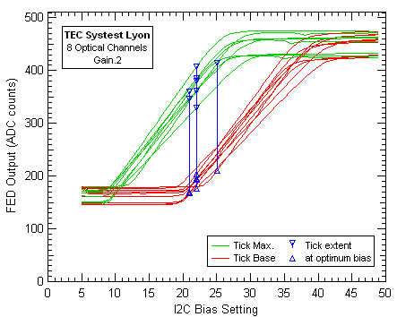 By taking the difference you find the amplitude of the tick: 
Assuming an amplitude of 800mV for the tick at the input to the AOH one can calculate the optimal settings for both Gain and thus Bias settings. The FED has a gain of ~3.5mV/count (based on the measurement of a single FED at CERN - you should check the gain of your own FED). The nominal gain of the optical link is 0.8V/V, so you should set your link so that the ticks amplitude at the FED is in the range 150-210 ADC counts. Having set your laser driver gain to achieve this, you can find the optimum bias setting using the procedure defined by Benjamin:
|
|
|
| Last modified by JT: Fri, 21-Feb-2003 14:11 |