|
|
|
|
|
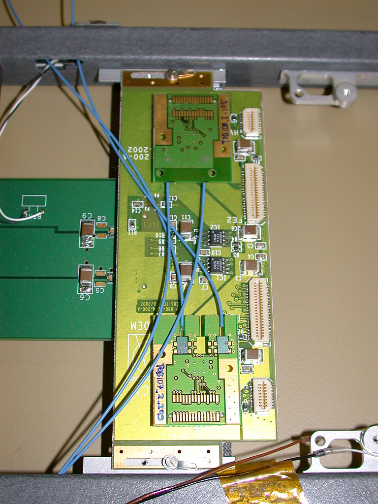
1.
TOP/ICC1/OP1 & OP2 installed, fibres routed to outside of ROD
|
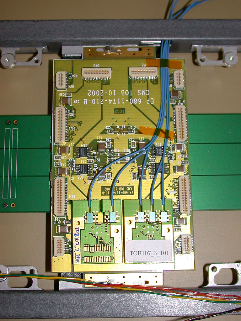
2.
TOP/ICC2/OP1 & OP4 installed, fibres routed to outside of ROD
|
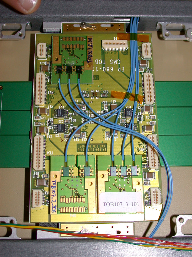
3.
TOP/ICC2/OP1, OP4, & OP3 installed, fibres routed to outside
of ROD
|
| |
|
|
|
|
|
|
|
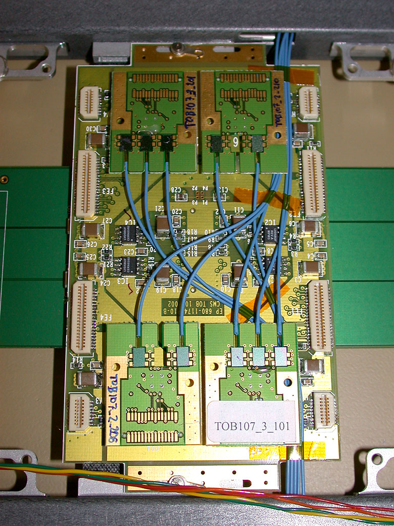
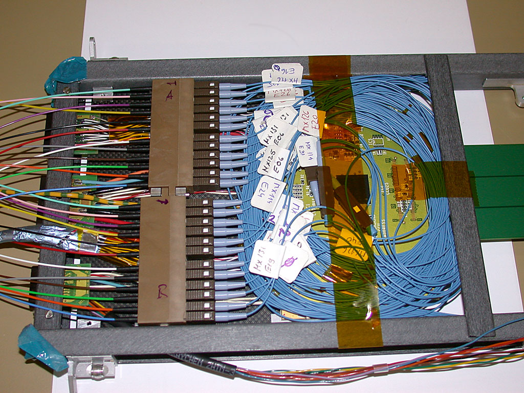
4.
TOP/ICC2/OP1, OP4, OP3 & OP2 installed, fibres routed in final
positions, held with kapton tape
|
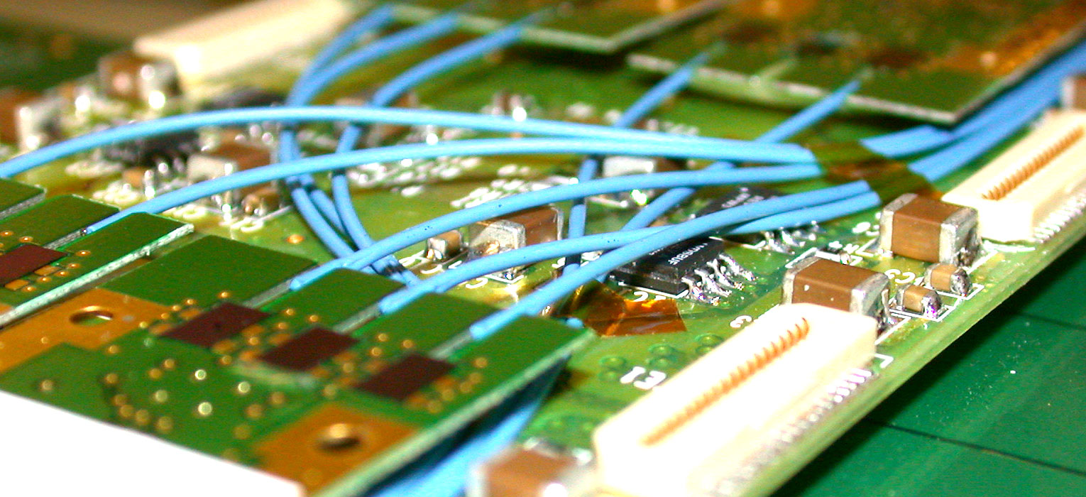
5.
Details of fibre routing for TOP/ICC2
|
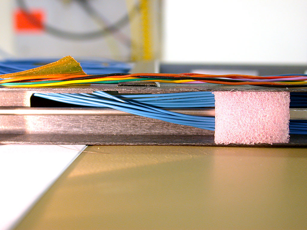
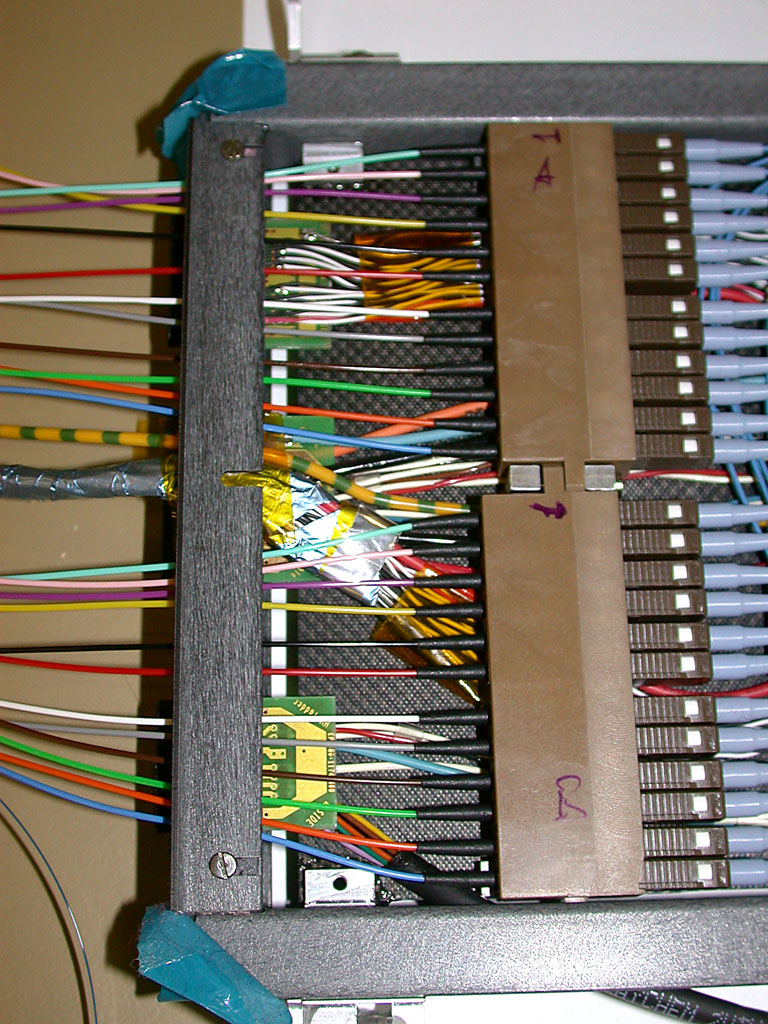
6.
Fibre routing from TOP/ICC1 (coming from OP2) along rod frame with
foam retainer
|
|
|
|
|
|
|
|
|
|
7.
Fibre routing from TOP/ICC2, joining fibres from TOP/ICC1 along
rod frame
|
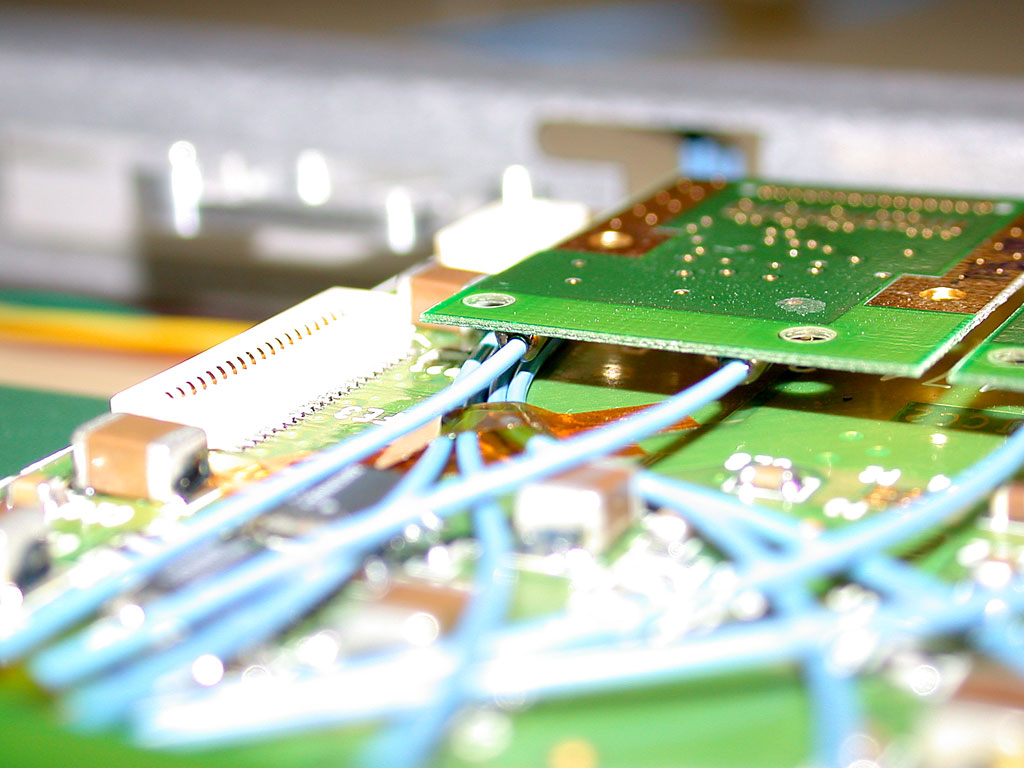
8.
Fibres from TOP/ICC1,ICC2 returning back into ROD above CCUM
|
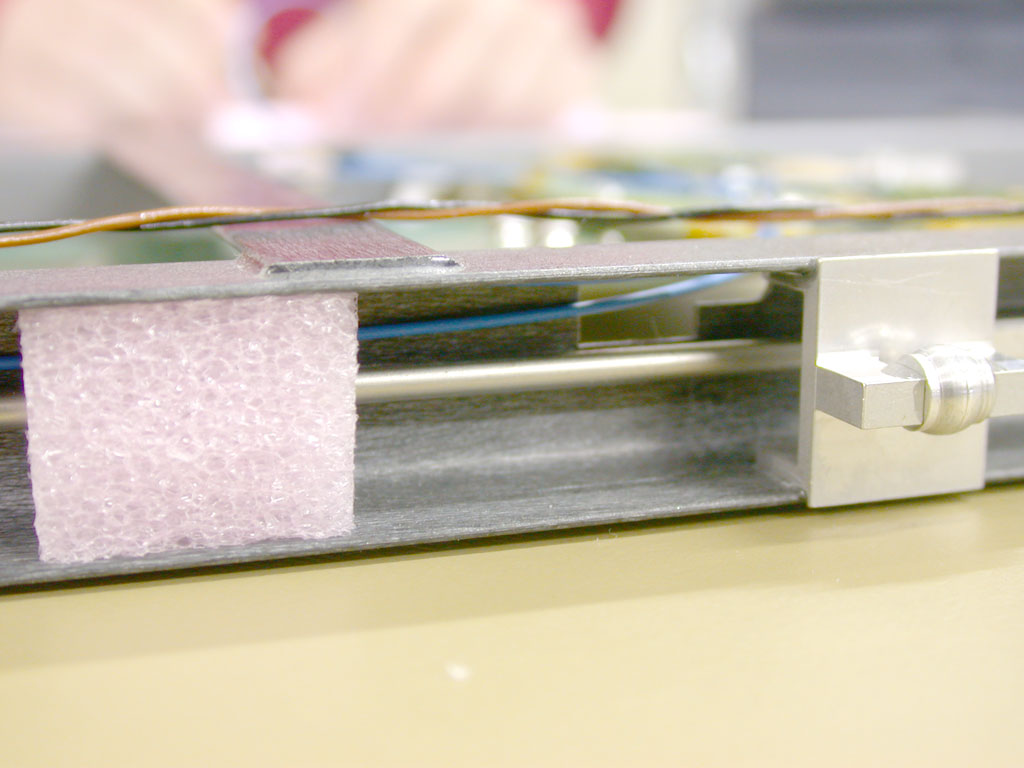
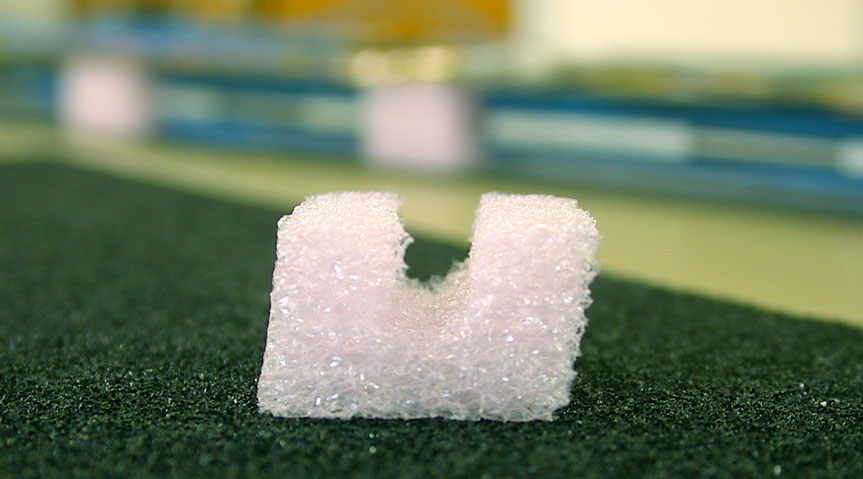
9.
Shaped foam fibre retainer
|
| |
|
|
|
|
|
|
|
10.
Potential problem routing area under AOH on ICC2
|
11.
Fibres from both TOP and BOTTOM faces exiting at CCUM
|
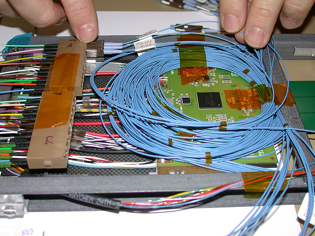
12.
Fibres coiled above CCUM, connection starting with sMU-MU adaptor
not mechanically fixed
|
| |
|
|
|
|
|
|
|
13.
All connections complete, fibre coils secured, sMU-MU adaptor mechanically
fixed to ROD
|
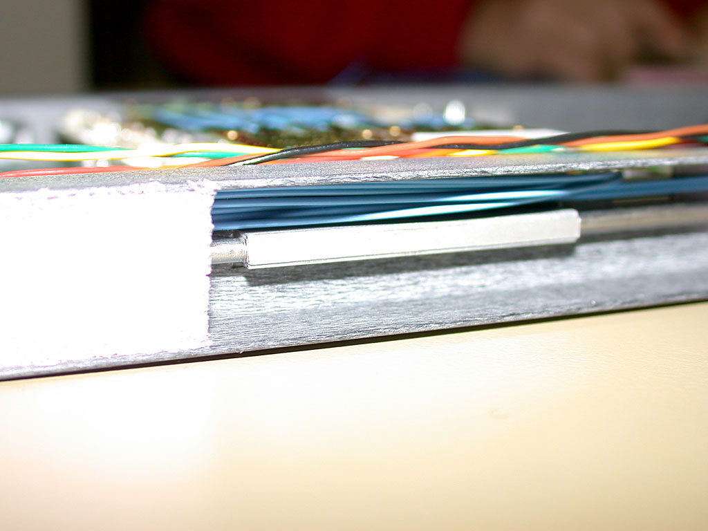
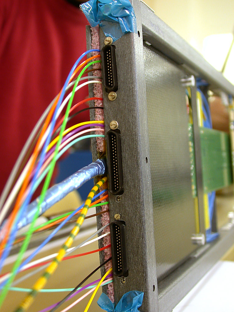
14.
Fibre/Cable exit clamp in position
|
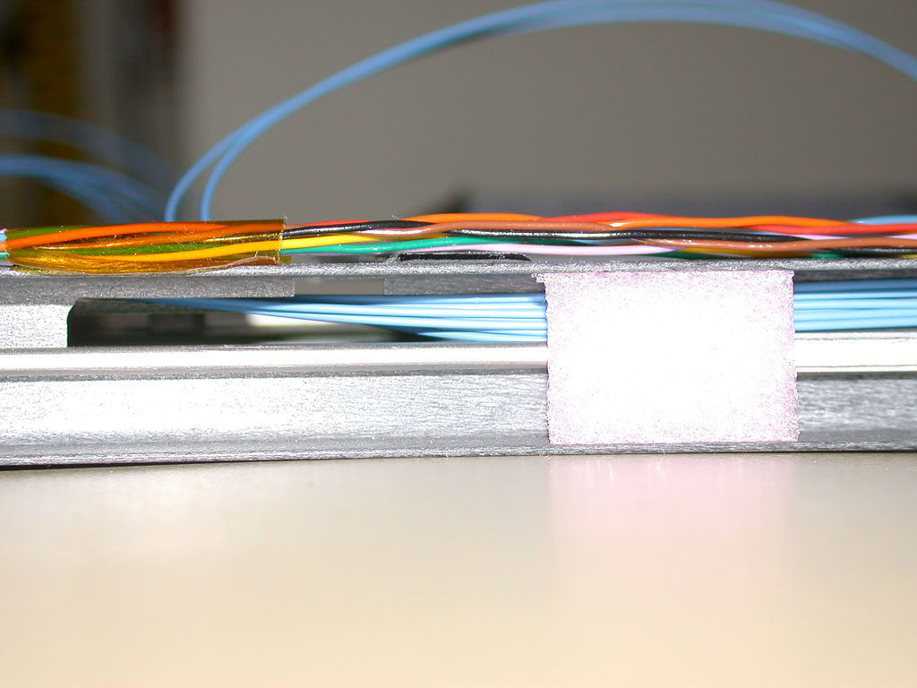
15.
Detail of fibre/cable clamp showing need for foam layer to clamp
fibre with substantially smaller diameter in comparison with CCU
ring cable
|